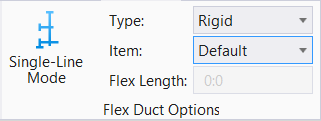
Single Line option
Allows for (centerline) preliminary routing.
As part of the duct sizing analytics, the single line workflow is introduced to shorten the time spent on doing preliminary routing of the system paths by making it extremely quick to establish basic routing paths and connections so that calculations can be run and the system size requirements can be established.
Schematic representation of routing eases effective design of HVAC system. The process often involve laying ducts, pipes, and connecting fittings. The entire route is drawn in a single line geometry with nodes added at turns and branches where the size and type fitting change along the route and end-caps at the terminal ends. The fittings and equipments are shown cell symbols.
Single line feature quickens creating systems without needing to change size or shape. Utilizes single click connections to outlets and vertical changes in elevation using AccuDraw making modeling a system easy. If you have preliminary information on the design intent and do change these things symbols and nodes are inserted at changes in direction, changes in size and changes in shape.
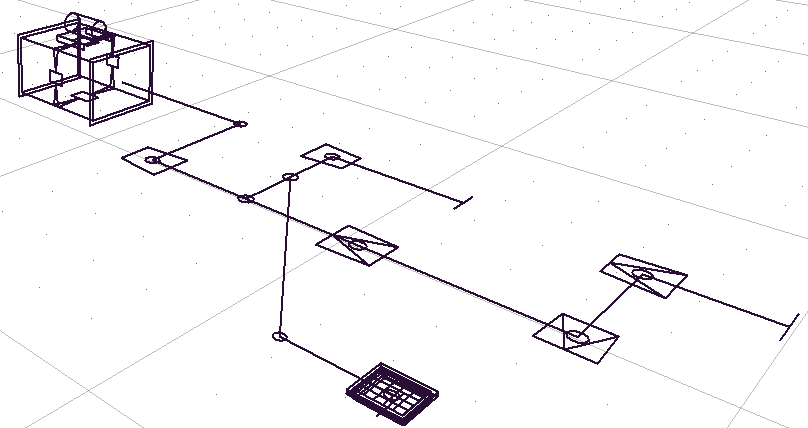
The system optimizes route by creating a vertical drop when connecting duct or pipe to fittings in elevated plane. This mode provides an easy way of creating a riser, say by placing a diffuser lower level and attaching it with single line. However, placing inline devices along the single line route doesn't visually break the continuity of the duct until it is promoted to 3D. Once the route and connections have been created the single line system can be loaded in the Duct Sizing System to calculate flows, losses and size information which will be written to the system.